
Question: What is a circuit breaker?
Answer: A circuit breaker is an automatic device that provides safety. In other words, it is a device designed to keep electrical and electronic equipment safe. When an excessive amount of current flows through a line, it can lead to accidents involving the equipment; a circuit breaker helps prevent such occurrences.

A circuit breaker consists of two contacts: a fixed contact and a moving contact. Under normal operating conditions in a power system, these contacts remain in a closed position, while under fault conditions, they open. The diagram illustrates the connections involving the current transformer (CT), relay and trip coil, which are used to operate the moving contact. An automatic mechanism, incorporating a trip coil is employed to actuate the moving contact of the circuit breaker. It is energized by the secondary current from the Current Transformer (CT) located on the line when the need arises. The moving contactor can be operated either via remote control or manually. When a fault occurs, an electric arc is generated the moment the circuit breaker contacts open automatically. Extinguishing this arc requires a certain amount of time. The primary function of a circuit breaker is to isolate the faulty section from the healthy part of the system and to extinguish the arc rapidly.
Question: List the names and uses of various types of circuit breakers.
Answer: SPCB = Single-pole Circuit Breaker,

DPCB = Double Pole Circuit Braker,

MCCB = Molded Case Circuit Braker,

MCB = Miniature Circuit Braker,

-
use for Instrument Safety
-
Use for Over Load Protection
-
Use for Short Circuit Protection
-
Use for 1/2/3/4 Pole
RCCB = Recidual Current Circuit Braker,

- Use for Earth falt Protection
- Use for Leakage Current Protection
- Use for 2/4 Pole
- Use for Humen Safty
ELCB = Earth Leakage Circuit Braker.

- Earthing is Mandatory
- Now it is not Use.
Question: State the differences between a fuse and a circuit breaker.
Answer: The differences between a fuse and a circuit breaker are as follows:
-
A circuit breaker has a faster response time than a fuse.
-
A fuse is much cheaper than a circuit breaker.
-
A circuit breaker can also function as a switch.
-
If a fuse blows, its wire must be replaced to restore the circuit, whereas a circuit breaker can simply be switched back on.
Question: What is a magnetic contactor? How does it work?
Answer: A magnetic contactor is an electromagnetic switching device.
It is typically used for controlling three-phase motors and is widely utilized in industrial settings.
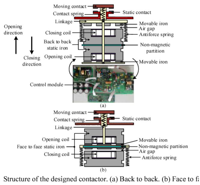
The operation of a magnetic contactor is quite similar to that of a relay; however, while relays are used for low-power or low-voltage connections, magnetic contactors are employed for high-power or high-voltage connections.
-
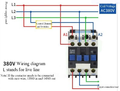
Like a relay, it contains an internal coil. These coils can be of either AC or DC type. The coil terminals are typically designated as A1 and A2. Common voltage ratings for these coils include AC 220V, 360V, and 440V, as well as DC 24V, though other voltage ranges are also possible.
-
For a three-phase connection, it features terminals labeled (L1, L2, L3 & T1, T2, T3 or alternatively, R, S, T & U, V, W). The three-phase power supply is connected to the top terminals (L1, L2, L3), while the three-phase motor is connected to the bottom terminals (T1, T2, T3). Additionally, it includes auxiliary contacts: NO (Normally Open) and NC (Normally Closed).
-
As soon as power is supplied to the magnetic contactor's coil, the Normally Open contacts close and the Normally Closed contacts open; this action, in turn, operates any connected auxiliary devices. This is how a magnetic contactor functions.
Question: What is an Overload Relay?
Answer: An overload relay is a cost-effective device used to protect critical and expensive motors. It provides reliable protection for the motor in the event of current or voltage overloads, excessive temperatures or phase faults.

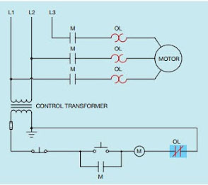
An overload relay provides protection for an electric motor, while a circuit breaker is used to protect the entire circuit and a magnetic contactor is employed for motor control.
Question: What are the different types of overload relays? Please provide definitions.
Answer: Based on the time it takes to provide an indication after an overload occurs, overload relays can be categorized into three types:
-
Class 10
-
Class 20
-
Class 30
The class numbers indicate the response time (in seconds). This information is typically specified on the overload relay itself; if it is not explicitly stated, it should be assumed to be Class 20.
Based on their operating principle, overload relays can be categorized into two types:
-
Thermal overload relay
-
Magnetic overload relay
- Thermal overload relay: This is a protective device used for electric motors; it cuts off the power supply if an excessive current flows through the motor for a specific duration. It typically utilizes a thermocouple, which heats up due to the flow of excess current and triggers the relay to switch off.

- Magnetic Overload Relay: This device operates by detecting the strength of the magnetic field generated by the current flowing through a motor. If an excessive current flows through the motor for a specified duration, the resulting magnetic flux pulls a core, causing the overload relay to trip (or switch off).
Question: What is the main difference between a thermal overload relay and a magnetic overload relay?
Answer: The main difference between a thermal overload relay and a magnetic overload relay is that a magnetic overload relay depends on the current flowing through it, rather than on the ambient temperature.
Question: What is a fuse? What is it made of?
Answer: A fuse is a short, thin conducting wire with a low melting point, which is connected within an electrical circuit to carry a specific amount of current. Various materials are used as the 'fusing element' (the material from which the fuse wire is made), including copper, silver, tin, zinc, antimony, aluminum and lead.

When the current flowing through a circuit exceeds a specific limit, the fuse melts, thereby disconnecting the circuit from the power supply. Fuses are used to prevent the occurrence of dangerous situations, such as the outbreak of fire outside the electrical circuit.
Question: How many types of fuses are there, and what are they?
Answer: Based on their construction, there are seven types of fuses:
1. Re-wireable

2. Cartridge
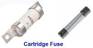
3. High Rupturing Capacity (HRC)


4. Carbon tetra-chloride fuse:


5. Drop-out fuse:

6. Expulsion fuse:

7. Horn gap fuse:

Based on voltage, there are two types of fuses:
1. Low-voltage

2. High-voltage

Question: What is the function of an Auto-Recloser?
Answer: With the increasing global consumption of electrical energy, interconnected power systems have expanded. In almost every country, power supply systems are integrated into a grid. When a fault occurs within an interconnected system, the circuit breakers at both ends trip and remain in a disconnected state until the fault is cleared—a situation that is undesirable for maintaining an uninterrupted power supply.
In power supply and distribution systems, most faults on overhead lines are transient that is, temporary in nature. Studies indicate that approximately 90% of such faults caused by factors like lightning, birds or tree branches coming into contact with the lines resolve themselves automatically after a very brief interval. In such cases, a standard circuit breaker trips as soon as a fault occurs; however, it does not automatically reconnect the circuit once the fault has cleared instead, it requires operator intervention to restore the connection. Therefore, to overcome this limitation and ensure an uninterrupted power supply, an auto-recloser is used.
Pole-mounted auto-recloser

Internal auto-recloser for the home

Auto-recloser

An auto-recloser is essentially a circuit breaker equipped with a mechanism to perform automatic reclosing a specified number of times at set intervals.
If a fault occurs on the line, the device disconnects and then reconnects the line after a brief interval (typically 0.3 seconds). If the fault persists after three consecutive attempts, the device will not reconnect the line. In this process, the recloser takes between 15 and 120 seconds to complete each of the three open-to-close cycles. If the breaker trips even after these three attempts, it will remain in the open position and will not close again. In such a case, it is assumed that a major, permanent fault has occurred on the line.
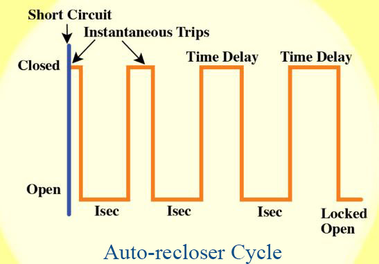
In such cases, the line fault must be identified and repaired in the presence of an operator before the auto-recloser/circuit breaker can be switched back on. Transient faults are typically resolved automatically through the auto-recloser’s three successive attempts.
Generally, two types of auto-reclosing systems are in use:
1. Single-phase auto-reclosing
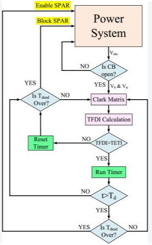
2. Three-phase auto-reclosing
Question: What is the function of an isolator?
Answer: An isolator is a type of switch that must be operated (turned on or off) only when there is no load. It lacks any specialized mechanism for arc extinction. An isolator cannot be opened while current is flowing through the circuit. If an isolator is opened while the circuit is carrying a significant load current, an electric arc is generated, which can easily lead to a flashover to the ground. This can damage the insulators on the pole as well as the contacts of the isolator itself. Furthermore, the resulting arc could cause a fire, potentially injuring the person operating the isolator.
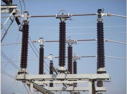
The types of isolators are as follows:
1. Vertical break type isolator
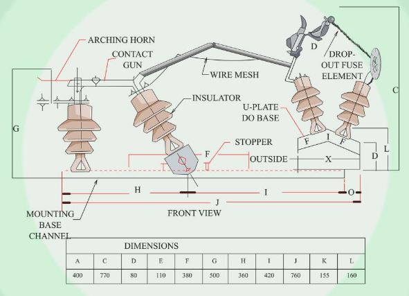
2. Horizontal-break type isolator (central-break or double-break type isolator)
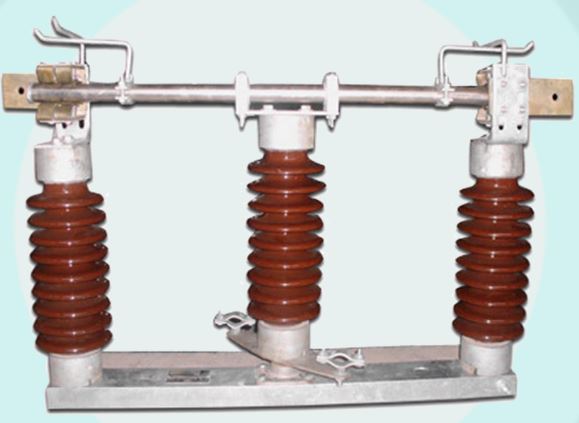
3. Vertical pantograph-type isolator
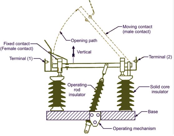
Procedures for opening and closing an isolator or circuit:
(a) Procedure for opening an isolator or circuit:
First, open the circuit breaker.
Then, open (or turn off) the isolator.
Finally, close the earthing switch (if present).
(b) Procedure for closing an isolator or circuit:
First, open the earthing switch (if present).
Then, close the isolator.
Finally, close the circuit breaker.
Question: What are some terms used in the analysis of circuit breakers?
Answer: Restriking Voltage: The transient voltage that appears across the terminals of a circuit breaker at the instant of arc extinction, and which tends to reignite the arc, is called restriking voltage.
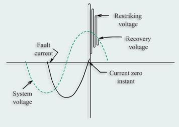
Recovery Voltage: When the oscillations of various harmonics are at their normal frequency, the effective voltage present at the pole terminals of a circuit breaker is called the recovery voltage. It is slightly lower than the rated circuit voltage.
Question: What is the function of a circuit breaker?
Answer: A circuit breaker automatically protects a circuit if the voltage exceeds the design voltage.
It acts in the following scenarios:
-
In the event of a short circuit in an AC line (line-to-line or line-to-neutral).
-
In the event of an overload.
-
In the event of an increase in voltage.
Question: What are the types of circuit breakers?
Answer: Based on the method of arc or fire extinguishing:
-
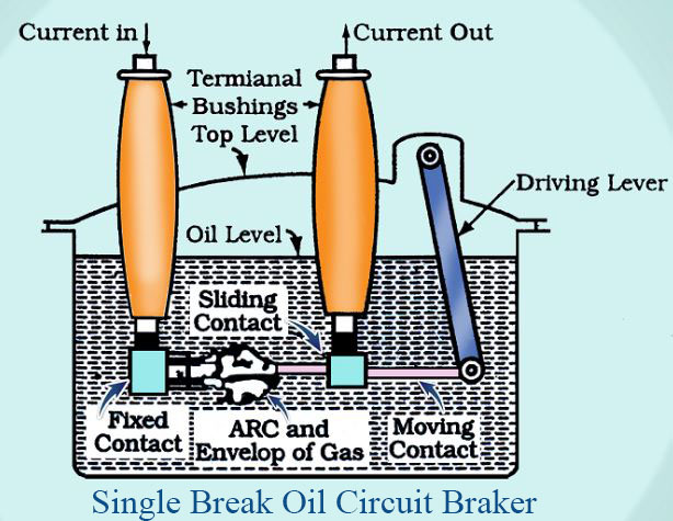
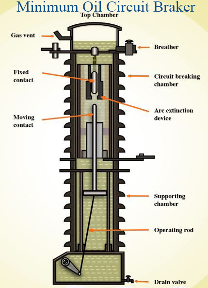
Oil Circuit Breaker: Oil circuit breakers are among the earliest types of circuit breakers. The primary reason for this is that mineral oil possesses better insulating properties—that is, a relatively higher insulating strength—compared to gas or air.

The comparative dielectric strengths of insulating materials used in various circuit breakers are presented in the table below: Insulating strength through arc extinction
Insulator |
Dielectric strength |
|
Wind |
3 |
|
Sulfur hexafluoride (uniform electric field) |
7 - 9 |
|
Silicone oil, mineral oil |
10 - 15 |
|
Vacuum |
20–40 (depending on the shape of the electrode) |
In an oil circuit breaker, mineral oil is used to insulate the various phases from one another and from the ground, as well as to extinguish the arc that forms when the conducting contacts are separated.
When an electric arc is generated within oil, a portion of the oil vaporizes, while another part decomposes to produce hydrogen (though other gases may also be present, hydrogen predominates). Consequently, the resulting arc becomes surrounded by hydrogen bubbles. These hydrogen bubbles assist in removing heat from the arc, which facilitates de-ionization and leads to the quenching of the arc.
The disadvantages of an oil circuit breaker include the flammability of the oil and the necessity for maintenance (i.e., oil replacement and purification).
Bulk Oil Circuit Breaker (BOCB): This is a type of circuit breaker that uses oil as an arc-extinguishing medium. The oil also serves as an insulator between the current-carrying components and the earthed parts of the circuit breaker. The oil used here is the same as the insulating oil used in transformers.
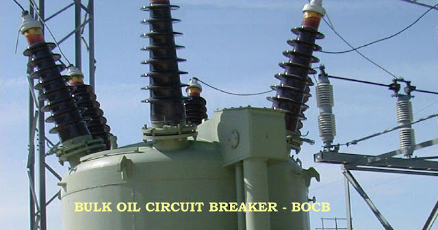
This circuit breaker can typically be used for voltages ranging from 1 kV to 330 kV.

Air Circuit Breaker:
A circuit breaker that uses air pressure to open and close the circuit is called an air circuit breaker.

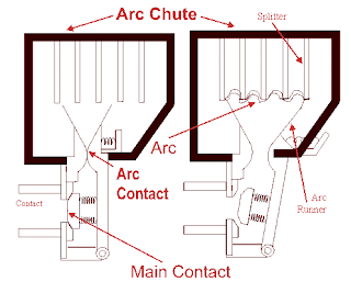
Classification:
In an air circuit, air is used to extinguish the arc. Based on the method of air usage, air circuit breakers are of two types:
1. Plain (or standard) air circuit breaker
2. Air-blast circuit breaker
1- Construction of a standard circuit breaker:
A standard circuit breaker consists primarily of two levers, an electromagnet, and a spring. The ends of the levers feature notches to facilitate their connection. Depending on the configuration, one, two, or three contact plates—corresponding to a single-pole, double-pole, or three-pole setup, respectively—are attached to the contact lever. A spring is connected to the contact lever, exerting force that tends to pull the contact plates away from their contact points.
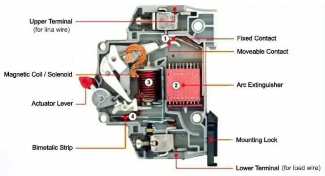
A spring is attached to the holding lever, which pulls the lever away from the magnet. The electromagnetic coil is connected in series with the line; alternatively, it may be connected via a current transformer. Typically, the entire assembly is housed within a steel enclosure. A knob or handle—made of plastic—is provided to operate the breaker by pressing the contact lever. When the button is pressed, the contact lever locks into place, and the contact blade closes the circuit. If an overcurrent flows, the holding lever is pulled down by magnetic attraction; consequently, the contact lever is disengaged by the tension of a spring, and the circuit is opened.
2. Air-Blast Circuit Breaker:
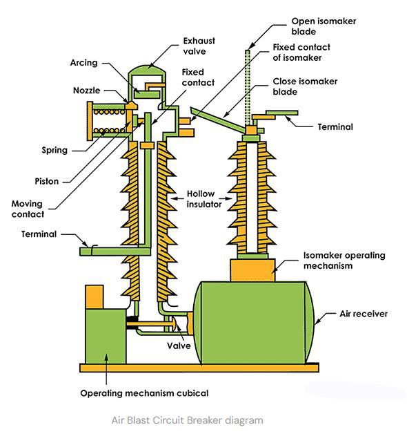
An air-blast circuit breaker features two fixed contacts located at the top of a porcelain bushing. A moving contact operates between these two fixed contacts to either close or open the circuit. The two fixed contacts serve as the terminals of the breaker. Attached to the moving contact is a plunger that moves up and down along the base of the lower chamber.
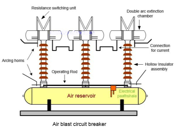
Three tubes are connected to the bushing. When air pressure is applied to the lowest tube, the plunger moves upward, closing the breaker. Applying air pressure to the middle tube pushes the plunger downward, causing the breaker to open. Air pressure is also directed toward the arc through a thicker tube located above this middle tube, which blows the arc away.
Air-blast circuit breakers are further classified into three types:
(i) Axial-blast circuit breaker: An axial-blast circuit breaker is a type of high-voltage air-blast circuit breaker (ABCB) in which a high-velocity flow of compressed air is directed longitudinally that is, along the axis of the arc path to extinguish the electric arc.
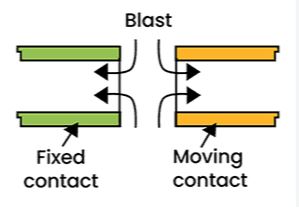
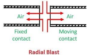
(ii) Radial-blast circuit breaker: A radial-blast circuit breaker is a type of air-blast circuit breaker (ACB) that utilizes a flow of high-pressure compressed air to cool and extinguish an electric arc; this air is directed from the center outward or across the arc in a radial direction.
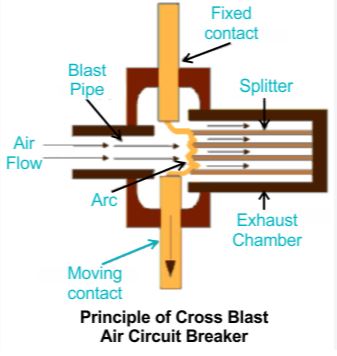
(iii) Cross-blast circuit breaker: A cross-blast circuit breaker is a type of air-blast circuit breaker that extinguishes an electric arc by directing a flow of high-pressure compressed air at a right angle (perpendicularly) to the path of the arc.
Usage:
1- This circuit is used to switch an electrical line on or off under normal operating conditions.
2- This circuit breaker is also used to protect electrical lines from damage caused by abnormal conditions. If a fault occurs anywhere in the line, the breaker trips and isolates the faulty section.
3- Standard air circuit breakers are used on the busbars on the load side of distribution transformers. Smaller-sized air circuit breakers are used in residential buildings, offices, hotels, and restaurants.
Sulfur Hexafluoride Circuit Breaker: A circuit breaker in which the current-carrying conductors operate within an environment of sulfur hexafluoride gas is called an SF6 circuit breaker. Sulfur hexafluoride is used due to its superior insulating properties.

This breaker consists of two main components:
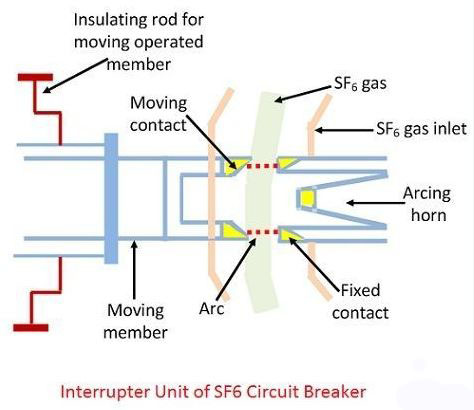
1. Interrupter unit: The interrupter unit is the core component of a sulfur hexafluoride (SF₆) circuit breaker, where the process of interrupting the flow of electricity and extinguishing the arc (electrical spark) takes place within a sealed, gas-filled chamber.
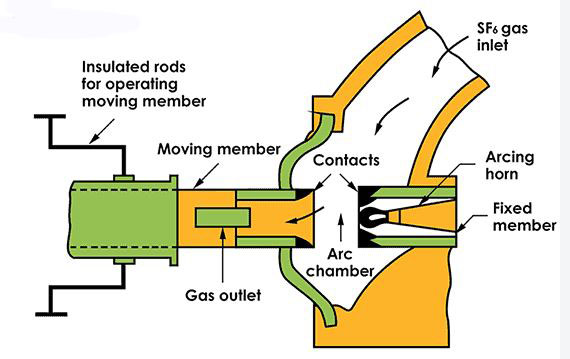
2. Gas System Unit: The gas system unit of a sulfur hexafluoride (SF6) circuit breaker is a closed-loop system designed to store, monitor, circulate, and manage high-pressure (SF6) gas. Given that (SF6) gas is highly expensive and possesses a significant global warming potential, this unit ensures that the gas remains securely contained. Simultaneously, it guarantees that the circuit breaker maintains the necessary dielectric strength and arc-quenching capability.
SF6 circuit breakers can be classified into the following categories:
a. Single-interrupter SF6 circuit breaker: A single-interrupter SF₆ circuit breaker is a high-voltage switching device that utilizes a single set of contacts and an arc-quenching chamber filled with sulfur hexafluoride (SF₆) gas to interrupt the flow of electricity in each phase and clear electrical faults.

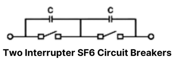
b. Two-interrupter SF6 circuit breaker: In a two-interrupter SF₆ circuit breaker, each phase consists of two sulfur hexafluoride (SF₆) interrupter units connected in series (typically arranged in a 'T-head' live-tank or a horizontal dead-tank configuration). It is used in medium- to high-voltage power transmission networks generally at voltage levels around 400 kV.
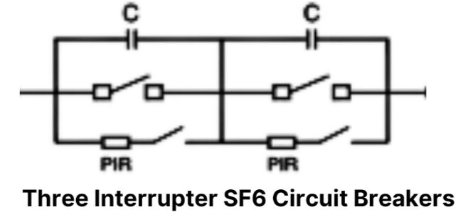
c. Three-interrupter SF6 circuit breaker: A three-interrupter SF₆ circuit breaker is an electrical switching device for high-voltage and extra-high-voltage (EHV/UHV) applications that utilizes sulfur hexafluoride (SF₆) gas and features three separate interrupting units connected in series for each phase (or three units housed within a single enclosure).
Vacuum Circuit Breaker: A circuit breaker capable of extinguishing an arc within a vacuum an environment devoid of matter is called a vacuum circuit breaker.

Arc: An arc is a type of electrical discharge that occurs between two conductive electrodes, producing a spark. The voltage that develops between the two electrodes as a result of this spark is known as the arcing voltage.
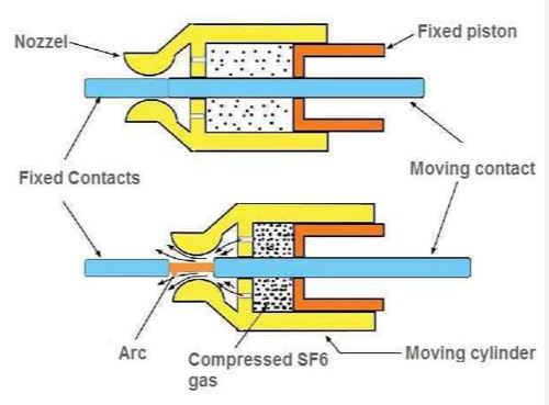
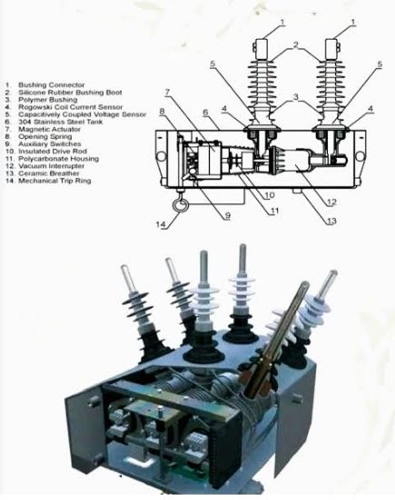
Use of Vacuum Circuit Breakers: These are typically used for 33/11kV distribution substations. However, the voltage rating for such circuit breakers can range from 3 kV to 38 kV. These vacuum circuit breakers contain a specific type of chamber known as a vacuum interrupter chamber.
Vacuum Interrupter Chamber: The chamber in which electrical contact plates are opened and closed and electric arcs are extinguished, is called a vacuum interrupter chamber. It is constructed from steel with a ceramic coating. The internal pressure within this chamber is 1 microbar. It contains copper and chromium contact plates. The design of these metallic plates has evolved over time; while butt-shaped (flat) plates were used initially, spiral-shaped plates are now widely employed.
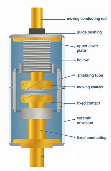
Operating principle of a vacuum circuit breaker: When a fault occurs in the power system to which a vacuum circuit breaker is connected, the two conductive contacts within its interrupter chamber separate from each other. During this separation, vapor is generated from the metallic components. An arc is then formed as a result of the polarization of this metallic vapor. When an arc is generated, ions or electrons position themselves on either side of the separated plates, creating a dielectric field. This quenches the arc, allowing the system to return to its normal state. If the distance between these chromium or copper plates is at least 2 cm, they can quench an arc of up to 30 kV.
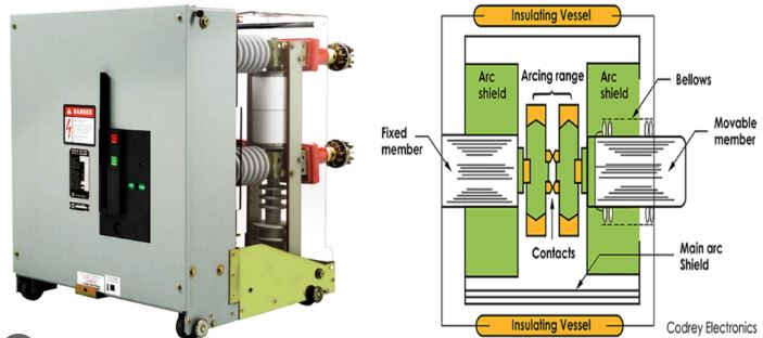
Advantages of a vacuum circuit breaker:
-
There is no risk of fire in the closed state.
-
It can withstand lightning strikes.
-
It requires minimal maintenance and operates silently.
-
It can have a long service life of up to 20 years.
-
The arc produced is of relatively low energy, and it does not generate any harmful gases.
Disadvantages of Vacuum Circuit Breakers:
-
A device for suppressing magnetizing current must be connected in parallel with the unit.
-
For voltages above 36 kV, maintenance becomes costly. Furthermore, if left open, air may enter the vacuum circuit breaker; this air can become ionized at high voltages, potentially leading to a fire or electrical breakdown. Therefore, it is essential to ensure that vacuum circuit breaker panels are kept in a completely airtight condition.
Based on their application, two types of vacuum circuit breakers:
- Outdoor circuit breakers: An outdoor circuit breaker is a high-voltage or medium-voltage switching device. It provides protection to electrical power systems, substations, and transmission lines against overloads, short circuits, and equipment faults.

-
Indoor circuit breaker: An indoor circuit breaker is an electrical protection device designed to safeguard a building's internal wiring, switchgear, and equipment from overloads and short circuits; it automatically interrupts the flow of electricity in the event of a fault. Since these are installed inside buildings within climate controlled environments or metal enclosures they are not subjected to harsh outdoor weather conditions, such as rain, ultraviolet (UV) radiation or extreme temperature fluctuations.

Based on the operating mechanism, three types of vacuum circuit breakers:
-
Spring-operated circuit breaker: A spring-operated circuit breaker utilizes the potential energy mechanically stored within a spring to rapidly open or close its electrical contacts. This design is widely employed in medium-voltage (MV) and high-voltage (HV) power systems such as in vacuum circuit breakers (VCB) and SF6 circuit breakers because it ensures rapid and reliable operation during emergencies, without requiring an external AC/DC power source.

-
Pneumatic circuit breaker: A pneumatic circuit breaker commonly known as an 'air-blast circuit breaker' (or a circuit breaker operated by a pneumatic/compressed-air-driven mechanism) utilizes a blast or flow of high-pressure compressed air (typically 20 to 30 kg/cm² or 20–30 bar) to extinguish the electric arc that forms when circuit contacts separate under load or fault conditions.

-
Hydro-electric circuit breaker: Depending on the scope of the system, a "hydro-electric" circuit breaker a term that may refer either to high-voltage circuit breakers used in hydroelectric power plants or to hydraulic-magnetic circuit breakers designed for specific types of current protection can be categorized into two primary practical contexts: high-voltage circuit breakers for hydroelectric power plants and hydraulic-magnetic circuit breakers.

Based on the voltage label installation: three types of vacuum circuit breakers:
-
High-voltage circuit breaker: A high-voltage circuit breaker is a robust mechanical switching device used in power transmission and distribution systems typically operating at voltages ranging from 1,000 volts to 1,200 kilovolts to control the flow of electricity and to automatically disconnect the circuit in the event of an electrical fault.

-
Medium-voltage circuit breaker: A medium-voltage (MV) circuit breaker is an electrical switching and protection device designed for alternating current (AC) systems operating in the 1 kV to 52 kV range (most commonly 10 kV to 35 kV).

-
Low-voltage circuit breaker: A low-voltage circuit breaker is an automatic electrical switching and protection device designed for use in circuits with an AC voltage of less than 1,000 volts (or a DC voltage of up to 1,500 volts). Its primary function is to monitor the flow of electricity and automatically cut off the power supply if any abnormal condition—such as an overload or a short circuit—is detected. In doing so, it helps prevent damage to equipment, electrical fires, and other safety hazards.

Additionally, vacuum circuit breakers can be classified as follows:
-
Magnetic circuit breaker: A magnetic circuit breaker is an automatic electrical protection device that disconnects the power supply in the event of a short circuit or excessive current flow; it protects wiring, panels and equipment from damage.

-
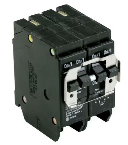
Common-trip circuit breaker: A 'common-trip' circuit breaker is a multi-pole electrical device (such as a 2-pole or 3-pole breaker) in which the internal mechanisms are physically linked so that, if a fault or overload occurs on any one pole, all poles disconnect (open) simultaneously.
-
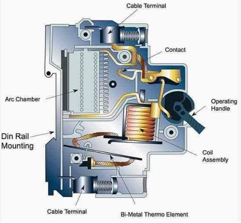
Thermal circuit breaker: A thermal circuit breaker is an electrical protection device that automatically disconnects the electrical connection in the event of excess heat caused by an excessive flow of electric current.
-
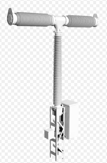
Disconnecting circuit breaker: A Disconnecting Circuit Breaker (DCB) is a modern high-voltage switchgear device that combines the active fault-clearing capability of a circuit breaker with the safety isolation functionality of a disconnector, all within a single, integrated unit.
-
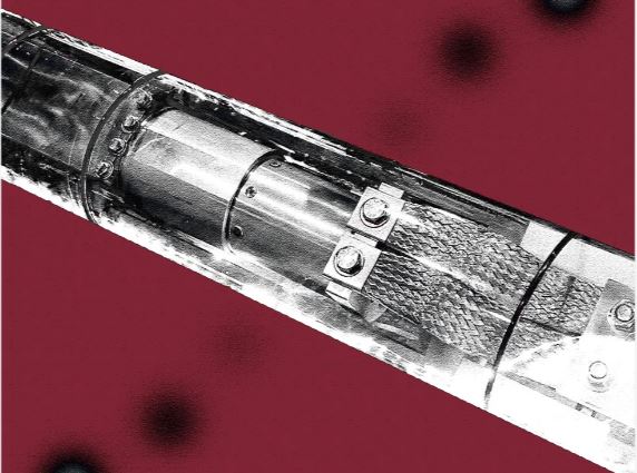
Carbon dioxide circuit breaker: A carbon dioxide (CO2) circuit breaker is a high-voltage electrical switch that uses high-pressure carbon dioxide gas—instead of sulfur hexafluoride (SF6) to extinguish electric arcs and clear faults in the electrical grid.
And others.
Question: Describe the construction and working principle of a circuit breaker.
Answer: Circuit Breaker: A circuit breaker primarily consists of two main parts:
-
Fixed contact.
-
Moving contact.
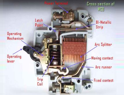
In our homes, we typically use an MCB (Miniature Circuit Breaker). An image of a miniature circuit breaker is provided below.
This is a circuit breaker that is widely used in residential settings. The image shows components such as the operating lever, arc splitter, moving contact, fixed contact, and trip coil.

Operating Principle of this circuit Breaker: Some basic operating principles of a circuit breaker are outlined below.
-
Under normal conditions, a circuit breaker is operated manually (or via remote control or other means).
-
In the event of a current fault, the circuit breaker operates automatically.
-
Under normal conditions, the moving and fixed contacts remain in contact with each other, allowing electricity to flow through the circuit.
-
Both the CT (Current Transformer) and the relay facilitate automatic interruption (in the event of a fault).
Question: What are the operating steps of a circuit breaker?
Answer: When the current flowing through a line exceeds the design current (due to an overcurrent fault), the current transformer (CT) steps down this excess current and sends it to the relay coil.
When the current in the relay coil reaches a threshold (exceeding a specified limit), the relay coil is activated, and the relay's moving contact interrupts the circuit.
At this point, the trip coil is energized via the battery source of the trip circuit, causing the contacts to open (break).
Question: What are the tests performed on a circuit breaker?
Answer: Tests for circuit breakers: When a circuit breaker is designed and manufactured according to specific requirements, testing is necessary to verify or validate various aspects of its performance.
The different types of tests are as follows:
(a) Type Test: A type test is conducted after the design of a circuit breaker has been finalized, in order to verify the ratings of the initial unit(s) and to validate the characteristics of that specific design. This test is not performed on every individual circuit breaker manufactured by a company.
The various types of type tests are as follows:
1. Mechanical test: Mechanical testing of a circuit breaker involves verifying the physical and functional integrity of its moving parts, operating mechanism, and linkage system to ensure that it can reliably open and close. Given that approximately 50 percent of switchgear failures are attributed to defects in the operating mechanism, mechanical testing serves as a critical step—both during type-testing at the factory and as part of routine maintenance in the field.
2. Temperature-rise test, millivolt drop test: A temperature-rise test (also known as a 'heat-run' test) is a standard engineering evaluation used to determine how much the temperature of electrical equipment increases relative to the ambient temperature when a specified electrical current or load is passed through it. and
A millivolt drop test is an electrical diagnostic procedure used to measure the slight reduction in voltage (in millivolts, or mV) that occurs across an electrical connection, joint, switch, or conductor when a specific amount of current flows through it. It assesses the quality of electrical connections and helps identify hidden resistance-related issues problems that could otherwise lead to overheating or connection failure in the future.
3. High-voltage test: Testing of high-voltage (HV) circuit breakers ensures the reliable performance, dielectric strength, and mechanical integrity of switchgear within an electrical power system.
4. Short-circuit Test: A short-circuit test verifies a circuit breaker's ability to safely make, carry, and break high fault currents without any mechanical failure or permanent damage.
Tests included under Short-circuit tests:
(i) Making capacity test
(ii) Breaking capacity test
(iii) Short-time test
(iv) Operating sequence test
(b) Routine Test: Tests conducted by the manufacturer on all circuit breakers of the same specification prior to their dispatch are known as routine tests.
Tests included under routine tests:
1. Operation test
2. Millivolt drop test
3. Power-frequency voltage test (at the manufacturer’s premises)
(c) Development Test: In this stage, manufacturers, researchers, and scientists examine the circuit breaker—either in its entirety or specific components and materials—to verify its suitability.
(d) Reliability Test: This test evaluates whether the circuit breaker can function accurately and reliably under various adverse conditions, such as seismic activity, ambient temperature fluctuations, exposure to dust, humidity, and repeated operation. This testing is typically conducted in a laboratory environment.
(e) Commissioning Test: This test is conducted after the installation of a circuit breaker. It verifies whether the circuit breaker has been installed correctly and is ready for operation.
The following tests are included as part of the commissioning test:
1. Mechanical operation test
2. Contact movement test
3. Insulation resistance test (resistance test between pole terminals)
4. Pre-commissioning check
5. Checking operation by triggering it with a manual operating signal.
6. Checking operation by energizing the relay.
(F) Short-circuit tests: These tests are conducted at a testing station to verify the ratings of a circuit breaker.
There are two types of such testing stations:
1. Field-type testing station
2. Laboratory-type testing station
Field-type testing station: In this type of testing, the circuit breaker under test is connected to the system, and power is supplied directly from a large-scale power system.
Laboratory-type testing station: In this type of testing, the required power is drawn from specially designed generators.