
Question: What is Power Factor?
Ans: Power Factor is the cosine of the angle between current and voltage.
In electrical engineering, the power factor is the ratio of active power to apparent power. It is represented by cosθ and its value can range from 0 to 1. The power factor indicates the percentage of electrical power that can be utilized for productive work. Active power is measured in kilowatts (kW), while apparent power is measured in volt-amperes (VA).
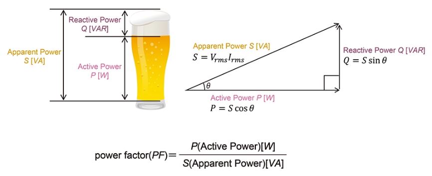
Here, active power refers to the amount of electrical power that we can actually use, while apparent power is the total power, representing the sum of active power and reactive power.
Power factor(PF) = Real Power (kW) / Apparent Power (kVA)
There are three types of power factor, namely:
-
Lagging Power Factor
-
Leading Power Factor
-
Unity Power Factor
Lagging Power Factor:
When the inductive load in a circuit exceeds the capacitive load, the power factor of that circuit is referred to as a lagging power factor. In other words, a circuit in which the current lags behind the voltage is said to have a lagging power factor.
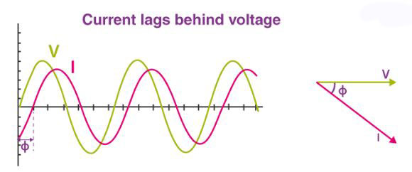
OR, When the current in a circuit trails behind the voltage (i.e., it lags relative to the voltage), the power factor of that circuit is referred to as a 'lagging power factor'. If a circuit is inductive, its power factor is lagging. Loads such as coils, motors, and lamps are inductive in nature, and they exhibit a lagging power factor.
Leading Power Factor:
When the capacitive load in a circuit exceeds the inductive load, the power factor of that circuit is called a leading power factor. In other words, a circuit in which the voltage lags behind the current is said to have a leading power factor.
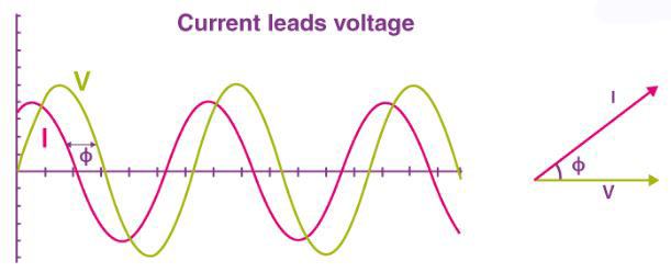
OR, When the current in a circuit leads the voltage, the power factor of that circuit is referred to as a 'leading' power factor. The power factor of a capacitive circuit is of a leading nature. Capacitor banks and synchronous condensers are examples of capacitive loads that have a leading power factor.
Unity Power Factor:
When the amounts of inductive load and capacitive load in a circuit are equal, the power factor of that circuit is called a unity power factor. In other words, a circuit in which there is no lagging or leading between voltage and current is said to have a unity power factor. In this case, the phase angle (Ø) between voltage and current is zero (Ø = 0), resulting in a power factor (pf) of 1.
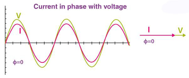
OR,

What happens when the power factor is low:
-
Excess current will flow through the circuit.
-
Line losses (copper losses) will increase.
-
Voltage drop will occur in the circuit.
-
The efficiency of the power system will decrease.
-
Electricity bills will be higher.
-
A low power factor may result in financial penalties.
-
If the power factor drops significantly, it can damage the devices used in homes and factories.
Alternating current (AC) power has three components:
-
Real power or active power, expressed in watts
-
Apparent power, expressed in volt-amperes
-
Reactive power, expressed in reactive volt-amperes
Power Factor Correction:
In simple terms, power factor correction refers to the process of reducing the amount of reactive power in a system while increasing the amount of active power. We typically correct and improve the power factor by using capacitor banks or synchronous motors. In industrial settings, capacitor banks are used for power factor correction.
Generally, the power factor can be improved in three ways. These are:
-
By using a static capacitor bank;
-
By using a synchronous condenser; and
-
By using a phase advancer.
Static Capacitor Bank Method:
When the inductive load increases significantly, the power factor decreases. However, if we connect a capacitor in parallel, the power factor increases (improves).

Factories use a Power Factor Improvement Unit (PFI), which automatically improves the power factor through the static capacitor bank method.
Synchronous Condenser Method:
By adjusting the rotor excitation, a synchronous motor can be operated at either a lagging or a leading power factor. Consequently, a synchronous motor can be used to improve the power factor. However, this method is highly expensive and is, therefore, no longer in use.

Phase Advancer Method:
This is connected to the rotor circuit of an induction motor. When the induction motor is started, an additional current is supplied from an external source to the rotor circuit, which reduces the power factor of the induction motor's rotor.

N.B: We know that when the power factor of a line falls below a specified value, raising it back to that specified level is known as "power factor improvement."
For residential settings, the power factor (PF) is 0.9 – 0.95.
For industrial settings (factories), the power factor (PF) is 0.8 – 0.85.
Question: What do we mean by a Power Factor (cosφ) = 0.7?
Ans: A Power Factor (cosφ) = 0.7 means that if the supply power in a given line is 100 kVA, then 70 kW of active power will be obtained.
Example 01: A 60 kW load with a power factor (pf) of 0.8 is connected to a 3-phase, 440V line. What should be the rating of a static capacitor bank to be connected in order to improve the power factor of this load to 0.9?
Ans: We have,
CosØ1 = 0.8, TanØ1 = sinØ1/CosØ1 = (1 - Cos2Ø1)1/2 / CosØ1 = (1 - (0.8)2)1/2 / 0.8 = 0.75
CosØ2 = 0.9, TanØ2 = sinØ2/CosØ2 = (1 - Cos2Ø2)1/2 / CosØ2 = (1 - (0.9)2)1/2 / 0.9 = 0.48
We Know,
KVAR = P ( TanØ1 - TanØ2) = 60 ( 0.75 - 0.48) = 16 KVAR
µF = (kVAR × 10⁹) / (2 × 3.141 × f × V²) = (16 × 10⁹) / (2 × 3.141 × 50 × (440)²) = 262.8 µF
For a 3-phase (3Ø) system, the value for each of the 3 capacitors would be = 262.8 / 3 = 87.6 µF
Now, if three 87.6 µF capacitors are connected in a Star or Delta configuration on a 3-phase (3Ø) line, the power factor will improve from 0.8 to 0.9.