
What is a busbar? Characteristics of a busbar and calculations for determining busbar size. Author: Engr. Dibakar Dey, IIT-Kharagpur, India.
Question: What is a busbar?
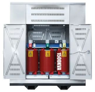
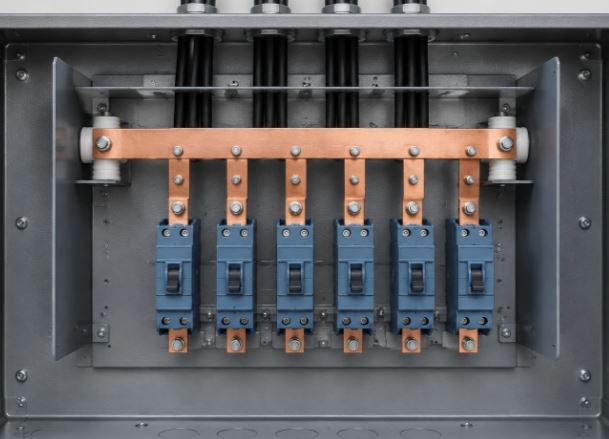
Answer: A busbar is a type of electrical conductor, typically a flat strip - made of copper, brass or aluminum. Busbars are most commonly used in industrial settings (factories). Electrical power from a transformer is fed into a busbar, which then carries the current. From the busbar, the power is routed to circuit breakers for use. To make connections, holes are drilled into the busbar and wires - fitted with lugs are secured to it using nuts and bolts.

The advantage of using busbars is that they allow for easy distribution of electrical connections to multiple locations. Those aspiring to work in factories must understand how to perform busbar calculations. Today, we will simplify the process of busbar calculation for you.

Busbars can be quite large but that is not the primary factor. The current-carrying capacity (amperage) of a busbar depends essentially on its height and thickness. Busbars typically come in four colors: red, green, and blue for the three phases, while black is used for the neutral.
Characteristics of a busbar:
-
It must be made of a material with low resistance.
-
It must be made of a material with high mechanical strength.
-
There must be provisions for expanding the busbar system.
-
The busbar must be rated for the specified current value.
-
It must be completely safe and well-constructed.
Types of busbars:
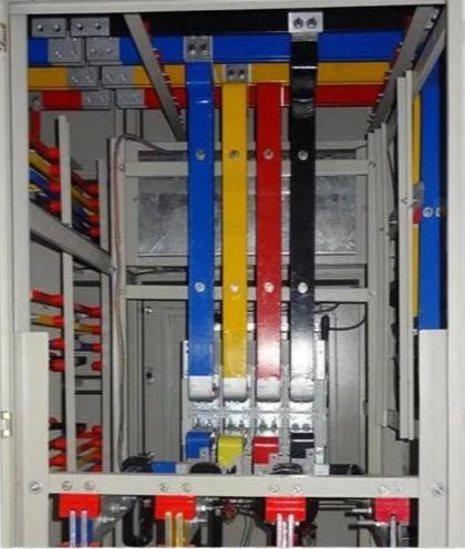
1. Indoor busbar: An indoor busbar system is a robust, centralized network of metallic conductors used within buildings specifically in switchgear panels and distribution boards to safely and efficiently transport high-intensity electrical power, serving as an alternative to the use of conventional, bulky cable bundles.
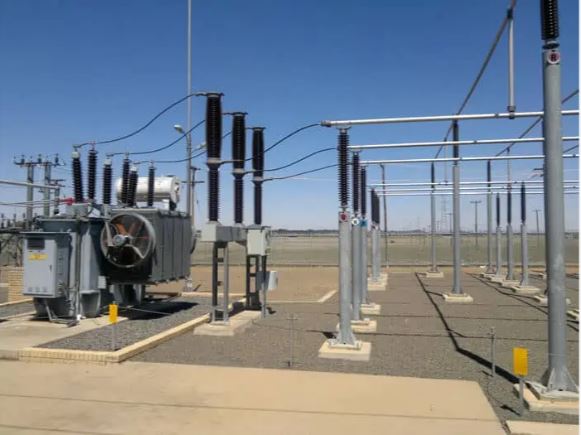
2. Outdoor busbar: An outdoor busbar system is a robust metallic conductor arrangement typically constructed from rigid copper or aluminum bars used for collecting and distributing high-power electrical energy within outdoor electrical switchyards, substations and industrial facility premises.
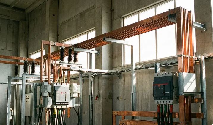
3. Open busbar: An open busbar system is a method of electrical power distribution in which metal conductive bars (typically made of copper or aluminum) are mounted on insulators and left exposed to the open air, rather than being enclosed within a protective metal or resin casing.
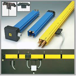
4. Enclosed busbar: An enclosed busbar system is an integrated and touch-safe method for electrical power distribution, in which rectangular copper or aluminum conductors are housed within a protective plastic or metal enclosure. It serves as a modern and safer alternative to traditional multi-cable or exposed wiring systems.
5. Oil-immersed busbar: An oil-immersed busbar system (also known as an oil-insulated or oil-filled busway) is a specialized arrangement for electrical power distribution, in which the main conducting bars (made of copper or aluminum) are kept fully submerged within a sealed tank containing highly refined dielectric mineral oil or synthetic oil.
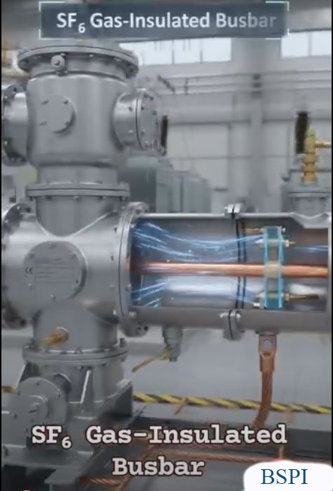
6. Pressurized gas-insulated busbar: A pressurized gas-insulated busbar (GIB) system is a high-voltage power transmission arrangement in which central conductors with high conductivity (made of aluminum or copper) are enclosed within a grounded metal casing, which is filled with a pressurized insulating gas.
7. Three-phase busbar without barriers in a common metal enclosure: In electrical engineering, a three-phase busbar system housed within a common metal enclosure without any internal partitions or barriers—is formally referred to as a 'Non-Segregated Phase Busduct' (NSPBD).
In this configuration, the three phase conductors (L1, L2, L3 or R, Y, B) along with a neutral bar, if required are all contained within a single metal enclosure, with no metallic partitions present to separate the phases. Instead of any physical or structural barriers, the air surrounding the adjacent phase bars serves as the primary insulating medium.
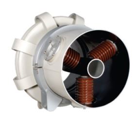
8. Isolated-phase busbar: An Isolated-Phase Bus (IPB) system is a specialized electrical busbar arrangement designed for high-current applications, in which each phase of a three-phase electrical system is enclosed within a separate, physically isolated, and grounded metal housing.
etc.
Various types of busbar arrangements:
1. Single busbar arrangement
2. Main and transfer busbar arrangement
3. Double busbar arrangement with double breakers
4. One-and-a-half breaker busbar arrangement
5. Ring main busbar arrangement
6. Sectionalized single busbar arrangement
7. Sectionalized double busbar arrangement
8. Mesh busbar arrangement
- Single Busbar Arrangement: In this arrangement, a single set of busbars is used for the entire system of a generating station. All generators, transformers, and feeders are connected to these busbars. In principle, all generators are connected to the busbars via circuit breakers and isolators. Transformers connected to outgoing feeders have isolators on both sides. This type of busbar arrangement is used in small AC generating stations as well as in DC stations.

Advantages:
1. Only one circuit breaker is required for each feeder, which reduces costs.
2. The relay arrangement is simple and straightforward.
3. Operational procedures are very easy.
4. Maintenance costs are lower due to the smaller number of circuit breakers.
5. The busbar voltage is used for relay operation.
Disadvantages:
1. If any problem arises with the busbar, the entire system must be shut down.
2. Regular maintenance of an active busbar is difficult; the entire system must be disconnected from the power supply to perform maintenance.
3. To repair or maintain a circuit breaker, the circuit connected to that breaker must be disconnected from the busbar.
4. When adding a new circuit to an existing busbar, the busbar must be completely disconnected from the power supply and de-energized using an earthing switch.
- Main and Transfer Busbar Arrangement: Most modern generating stations currently employ two busbars - a main busbar and a transfer (or auxiliary) busbar. Under normal operating conditions, the main busbar carries the load, while the transfer busbar remains in reserve. Should any issues arise with the main busbar, or if it requires repair or maintenance, the entire load can be shifted to the auxiliary or transfer busbar using a bus coupler.

Advantages:
1. It allows for an uninterrupted power supply.
2. Circuit breakers can be maintained without interrupting the power supply.
3. Circuits can be connected to any busbar.
4. This arrangement results in lower maintenance costs for the substation.
5. The busbar voltage can be used for the relays.
Disadvantages:
1. An accident may occur during the transfer of power from the main busbar to the auxiliary or transfer busbar.
2. Its operation is complex.
- Double-busbar arrangement with double breakers: Double-busbar arrangements are used in high-capacity and critical generating stations. In this type of double-busbar arrangement, each circuit is equipped with two circuit breakers; however, no bus coupler is required for transferring the supply. In this setup, the circuit breakers offer the highest level of maintenance convenience but the arrangement is very costly. Since there are two circuit breakers, if one requires maintenance, the other can carry the full load.

Advantages:
1. It offers maximum flexibility and reliability for the system.
2. Power interruptions during system issues or maintenance can be kept to a minimum.
Disadvantages:
1. The installation cost is relatively high.
2. The maintenance cost is high.
- One-and-a-half breaker busbar arrangement: In this configuration, three circuit breakers are used for every two feeders. Consequently, six circuit breakers are employed for four feeders. Since this results in an average of 6/4 = 1.5 circuit breakers per feeder, it is known as a one and a half breaker busbar arrangement.

Advantages:
1. This method is less expensive than the double busbar and double breaker arrangement.
2. Power supply is not interrupted in the event of a fault in a circuit breaker or a busbar.
3. This method allows for the connection of additional circuits.
4. In this arrangement, the busbar voltage can be used for the relays. However, if a fault occurs on a busbar, the relay connection must be disconnected and shifted to a fault-free busbar.
Disadvantages:
1. In the event of a busbar fault, two circuit breakers must be disconnected; consequently, relay operation is significantly more complex compared to a single busbar arrangement.
2. Maintenance costs are higher.
3. To perform maintenance or repairs on a circuit breaker without resorting to load shedding, two circuit breakers must be disconnected, leaving the power supply to be maintained through only one circuit breaker. As a result, if a fault occurs on the remaining active busbar, the entire power supply is interrupted.
- Ring Main Busbar Arrangement: The ring main busbar arrangement is an advanced version of the sectionalized double busbar system. In this configuration, bus couplers are installed at the two ends of the sectionalized double busbar, creating a ring-shaped connection. This makes the entire system highly flexible. With this setup, an alternator connected to any busbar section can be used to supply power to a feeder located in any other section.

Advantages:
1. Power can be supplied to all feeders from both directions at a low cost.
2. If a circuit breaker in any busbar section fails or develops a fault, only the affected circuit is isolated from the system, without impacting the other circuits.
3. Circuit breakers can be repaired and maintained without disrupting the power supply.
4. Since the number of circuit breakers required is comparable to that of a single busbar system, the cost of this arrangement is very low.
Disadvantages:
1. A separate supply voltage is required for each relay. When a circuit breaker is opened or disconnected in one section, the flow of power from the other direction may cause an overload on the feeders of other circuits, potentially leading to the tripping of their respective circuit breakers.
2. Adding a new circuit to the ring is difficult.
- Sectionalized Single Busbar Arrangement: In this arrangement, if any part of the busbar requires repair or maintenance, the supply can be disconnected only for the faulty section, without interrupting or disrupting the power supply to the entire system. To facilitate this, the substation busbar is typically divided into two or three sections, as required a configuration that depends on the system's short-circuit current. Bus couplers are used to divide the overall busbar into several distinct sections. A bus coupler is essentially a combination of a circuit breaker and an isolator. To protect the busbar sections on either side of the bus coupler from fire, fireproof walls are constructed around it. It should be noted that, during load sharing, both sections are synchronized before the bus coupler switch is closed.

Advantages:
1. If a fault occurs in any section of the busbar, that specific faulty section can be isolated from the system without disrupting the power supply to the remaining sections.
2. Only one additional circuit breaker is required, which keeps costs low.
3. Its operation is simple and straightforward.
4. Maintenance is easy and relatively inexpensive.
5. In this configuration, the fault current in each section is reduced, allowing for the use of lower-capacity circuit breakers for the feeders.
6. A potential busbar can be utilized for the line relays.
Disadvantages:
1. In the event of a fault on the busbar, power supply to half of the system is interrupted.
2. During routine maintenance, the supply to one section must be disconnected.
3. When a circuit breaker in any section requires maintenance, replacement, or modification, the corresponding busbar section must be taken out of service.
- Sectionalized Double Busbar Arrangement: In this system, there are two busbars—a main busbar and an auxiliary busbar. The main busbar is divided using a bus coupler. However, the auxiliary busbar is not divided, nor is there a need to do so, as partitioning it would be extremely costly.

Advantages:
1. Any part of this system can be maintained independently.
2. With the help of an auxiliary busbar, any one section can be synchronized with another section.
- Mesh Busbar Arrangement: A mesh busbar arrangement is one method used in substations to optimize the number of circuit breakers. In this configuration, circuit breakers are arranged in a mesh pattern along the busbar. Individual circuits are tapped off from the nodes (junction points) of this mesh. The illustration shows eight feeders being controlled by four circuit breakers. If a fault occurs in any part of the system, the relevant circuit breakers must be disconnected, which effectively opens the mesh connection. In this setup, eight circuits are controlled using only four circuit breakers.

Factors to consider when selecting a busbar:
1. It must allow for the operation of the entire plant or specific sections, as required.
2. Local conditions and the magnitude of the load must be determined.
3. The required level of operational flexibility must be established.
4. The size and configuration of the busbar must be determined.
5. Initial installation costs, operational and maintenance expenses, and ease of availability must be assessed.
6. Ease of maintenance and the safety of personnel must be ensured.
7. Simplicity and clarity in construction must be ensured.
8. Provision for future expansion must be included.
9. Safe areas must be clearly designated.
Calculating Busbar Size:
The size of a busbar depends on the load current. Load current can be determined in two ways:
kVA = 1000 × Voltage × Current
kW = 1000 × Voltage × Current × Cosφ
I = (kVA × 1000) / (√3 × Voltage) (For three-phase systems)
I = (kVA × 1000) / Voltage (For single-phase systems)
Example 01. For a 3-phase (3Ø) 150 kVA transformer with a voltage ratio of 1100/440 volts, what will be the current on the secondary side? Power factor (pf) = 0.9.
Ans: I1 = (kVA × 1000) / (√3 × Voltage) = (150 × 1000) / (√3 × 440) = 196.82 A.
I2 = (kW × 1000) / (√3 × Voltage × pf) = (150 × 1000) / (√3 × 440 × 0.9) = 218.69 A.
Including a 25% margin: I1 = 196.82 × 1.25 = 246 A.
I2 = 218.69 × 1.25 = 273.36 A.
Two types of electrical busbars:
-
Copper Busbar
-
Aluminium Busbar
Copper Busbar: Current Density = 1.5 ~ 2.0 A. This means that 1.5 ~ 2.0 A of current can flow through a 1 mm² copper busbar.
Aluminium Busbar: Current Density = 0.5 ~ 1.5 A. This means that 0.5 ~ 1.5 A of current can flow through a 1 mm² aluminium busbar.
If we use a copper busbar, its current density = 1.6 A.
Copper Busbar Size = 246 / 1.6 = 153.75 ≈ 154 mm²
If we assume the thickness of the copper busbar to be 7 mm, then the height = (154 / 7) = 22 mm.
Therefore, the size of the copper busbar for current I1 will be = 22 mm × 7 mm ........ (in the context of kVA)
---------------------------------------------------------------------
Copper Busbar Size = 274/1.6 = 171.25 ≈ 172 mm²
If we assume the thickness of the copper busbar to be 7 mm, then the height (172/7) = 24.57 mm ≈ 25 mm
Therefore, the size of the copper busbar for current I2 will be = 25 mm × 7 mm ........ (in the case of kW)
Example 02. Suppose your factory's transformer is supplying 600 amperes of current per phase. What size busbar should you install?
Ans: As mentioned earlier, the key factors for a busbar are its dimensions (thickness and width/cross-section)—the overall physical size is not the primary concern. Busbar measurements must always be specified in millimeters.
Busbar Calculation:
Let’s assume there is an 11/0.44 kV, 500 kVA three-phase transformer at an industrial facility. We need to select a busbar for the outgoing side to be installed in an LT (Low Tension) panel. Let’s perform the calculation.
Current I (secondary)
= 500 x 1000 / (1.732 x 440)
= 656 Amperes
Now, for greater safety, I need to add an extra 25%.
So, 656 x 1.25 = 820 A
If I use copper busbars, I should use 0.5 sqmm of busbar cross-section for every 1A of current. For aluminum, it should be 1.2 sqmm per ampere.
Therefore, if I use copper, I should use a 410 sqmm busbar for an 820-amp load.
However, you must check whether busbars of these exact dimensions are available in the market. Common busbar sizes available in the market include:
25 x 5, 25 x 8, 25 x 10, 30 x 5, 30 x 8, 30 x 10,
40 x 5, 40 x 8, 50 x 5, 50 x 8, 50 x 10, 80 x 5, 80 x 8, 80 x 10, 100 x 20, 110 x 10 mm, etc.
Therefore, for our load, using an 80 x 5, 40 x 10, or
50 x 8 mm busbar will be sufficient.